

Amateur Radio Bands Explained:
Amateur radio bands form the operational framework of radio communication, with each band defined by a specific frequency range and wavelength that determines how signals travel, how antennas must be built, and when communication is most effective. These physical relationships control propagation distance, signal strength, noise behavior, and overall communication reliability.
New to the hobby? Start with our Complete Guide to Ham Radio Fundamentals.
At the heart of band behavior is the relationship between frequency and wavelength. Because electromagnetic energy travels at a constant speed, higher frequencies produce shorter wavelengths, and lower frequencies produce longer wavelengths. This simple relationship determines antenna size, signal reflection from the ionosphere, ground wave behavior, and even how radio waves interact with buildings and terrain.
Understanding how frequency, wavelength, and propagation interact allows operators to predict band openings, choose effective antennas, and communicate reliably across local, regional, and global distances.
This guide explains the science behind wavelength, antenna resonance, sine wave behavior, ionospheric propagation, solar influence, and real-world operating performance across every major HF amateur radio band.
Quick Answer: What Determines Amateur Radio Band Performance?
Amateur radio band performance is determined primarily by wavelength, which controls propagation distance, antenna size, and how signals interact with the ionosphere and terrain. Lower frequencies travel farther and bend around obstacles, while higher frequencies support long-distance reflection during strong solar activity.
Quick Answer: Why Are Antennas Different Sizes for Different Bands?
Antenna size is directly proportional to wavelength. Efficient antennas are typically built as a fraction of the signal wavelength, commonly one-quarter or one-half wavelength. Lower frequencies require larger antennas because their wavelengths are longer.
Frequency and Wavelength Fundamentals
Frequency describes how many wave cycles occur each second and is measured in hertz (Hz). Wavelength is the physical distance between repeating points in a wave, such as crest to crest.
The relationship is defined by:
Wavelength = Speed of Light ÷ Frequency
Because the speed of electromagnetic radiation is constant, wavelength decreases as frequency increases. This inverse relationship controls nearly every aspect of radio system behavior.
Lower frequency signals have long wavelengths and tend to travel farther along the Earth’s surface. Higher frequency signals have short wavelengths and interact more strongly with atmospheric ionization.
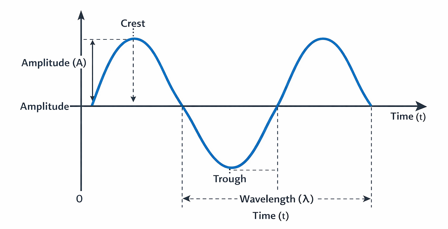
Understanding the Sine Wave in Radio Transmission
Radio signals propagate as sinusoidal electromagnetic waves. A sine wave represents smooth periodic oscillation of electric and magnetic fields. Every radio transmission — whether voice, digital data, or Morse code — is built from sine wave energy.
The mathematical form of a sine wave is:
y(t) = A sin(2πft + φ)
Where amplitude determines signal strength, frequency determines cycles per second, and phase describes timing offset. Complex signals can be broken into multiple sine waves through Fourier analysis, allowing engineers to manipulate and filter signals precisely.
Resonance and Antenna Efficiency
Antennas operate by resonance. When an antenna’s length matches a fraction of the signal wavelength, electrical energy transfers efficiently between the radio and free space.
Common resonant lengths include:
Quarter wave
Half wave
Full wave
If an antenna is not resonant, energy is reflected rather than radiated. This reduces signal strength and increases standing wave ratio (SWR). Proper antenna tuning ensures maximum radiation efficiency and reliable communication.
Why Wavelength Determines Antenna Size
Long wavelengths require long conductors to support resonance. This is why 160 meter antennas can exceed 100 feet in length, while 10 meter antennas may be only a few feet long.
Antenna height relative to wavelength also determines radiation angle. Lower radiation angles support long-distance communication, while high radiation angles support regional coverage.
How Wavelength Controls Propagation Behavior
Wavelength determines how radio waves interact with the environment.
Long wavelengths:
Diffract around terrain
Penetrate foliage and structures
Support ground wave propagation
Perform best at night
Short wavelengths:
Reflect strongly from ionosphere
Support long-distance skywave paths
Require higher solar ionization
Enable compact antenna systems
These characteristics explain why different bands perform best at different times.
The Ionosphere and Skywave Propagation
The ionosphere is a region of charged particles high in the atmosphere that reflects radio waves back to Earth. It consists of multiple layers that change with solar radiation.
The D layer absorbs signals during daylight.
The F layer reflects signals for long-distance communication.
When ionization is strong, high frequencies reflect efficiently. When ionization weakens, signals pass into space instead of returning.
Maximum Usable Frequency (MUF)
MUF is the highest frequency that will reflect back to Earth at a given time. It rises during strong solar activity and falls during low activity.
When MUF increases, higher HF bands open. When MUF decreases, high bands close and communication shifts downward.
Skip Distance and Radiation Angle
Signals transmitted at low angles travel farther before returning to Earth. This produces long-distance “skip” communication. High radiation angles produce short regional coverage.
Antenna height relative to wavelength largely controls radiation angle.
Near Vertical Incidence Skywave (NVIS)
NVIS propagation occurs when signals are transmitted nearly straight upward and return over a wide regional area. This technique provides reliable communication within several hundred miles and is widely used in emergency networks.
Gray Line Propagation
At sunrise and sunset, the gray line decreases ionospheric absorption while reflection remains strong. Signals traveling along the day-night boundary can propagate exceptionally long distances with minimal loss.
Solar Activity and Propagation Control
Solar radiation determines ionospheric density. Key indicators include solar flux, sunspot number, and geomagnetic activity.
High solar activity improves high-frequency propagation. Geomagnetic disturbances degrade signal stability.
Time of Day HF Band Performance Guide
| Time of Day | Most Effective Bands |
|---|---|
| Early morning | 40m, 30m |
| Daytime | 20m, 17m, 15m |
| Late afternoon | 20m, 40m |
| Evening | 40m, 80m |
| Night | 80m, 160m |
| Gray line | 20m, 40m, 80m |
Major HF Amateur Radio Bands and Their Behavior
160 Meter Band (1.8–2.0 MHz)
Extremely long wavelength produces strong ground wave and excellent nighttime long-distance propagation. Requires very large antennas and experiences high atmospheric noise.
80 Meter Band (3.5–4.0 MHz)
Primary regional communication band with reliable nighttime performance. Widely used for nets and emergency communication.
40 Meter Band (7.0–7.3 MHz)
Highly versatile band supporting both daytime and nighttime operation. Provides medium-distance communication with strong reliability.
30 Meter Band (10.1–10.15 MHz)
Narrow but stable band primarily used for CW and digital modes. Often less congested.
20 Meter Band (14.0–14.35 MHz)
Primary global DX band during daylight. Reliable worldwide communication under moderate solar conditions.
17 Meter Band (18.068–18.168 MHz)
Less crowded band offering balanced local and long-distance communication.
15 Meter Band (21.0–21.45 MHz)
High-efficiency DX band during strong solar cycles. Smaller antennas and long skip distances.
12 Meter Band (24.890–24.990 MHz)
Solar-dependent band capable of long-distance communication when open.
10 Meter Band (28.0–29.7 MHz)
Supports extremely long propagation during solar maximum. Rapidly changing conditions.
Quarter-Wave Antenna Length Reference
| Band | Quarter Wave Length |
|---|---|
| 160m | 130 ft |
| 80m | 66 ft |
| 40m | 33 ft |
| 20m | 16.5 ft |
| 10m | 8 ft |
Feedline Loss and Frequency
Signal loss in coaxial cable increases with frequency. Higher bands experience greater feedline attenuation, making low-loss cable increasingly important.
Polarization and Signal Orientation
Matching antenna polarization improves signal transfer. Horizontal polarization often reduces ground loss for long-distance HF communication.
Noise Floor and Signal-to-Noise Ratio
Lower frequencies experience higher atmospheric noise. Higher frequencies often have lower noise but greater fading.
Step-By-Step Method for Choosing the Best Band
1 — Check time of day
2 — Check solar activity
3 — Determine communication distance
4 — Select band matching propagation
5 — Tune antenna for resonance
Voluntary Band Plans
Operators follow informal frequency usage agreements for voice, CW, and digital modes to reduce interference and maintain order. The voluntary band plan lays out frequency portions you do not see on the average chart.
Common Operator Mistakes
Operating high bands at night
Ignoring solar conditions
Using non-resonant antennas
Remaining on one band too long
Practical Operating Strategy
Use low bands for stable nighttime communication.
The mid bands are good for consistent DX.
Use high bands during strong solar activity.
Frequently Asked Questions
Why do low frequencies work better at night?
Reduced ionospheric absorption allows stronger reflection.
Why do high bands open suddenly?
Solar radiation increases ionization and raises MUF.
Why is antenna tuning critical?
Resonance determines radiation efficiency.
About the Author
He primarily operates HF, knows propagation very well, operates mobile and handhelds daily. Vince exchanges QSL cards for DXCC, contest confirmation, and award tracking and is the club QSL manager. His guidance focuses on practical operating procedures, accurate logging, and real-world amateur radio practices.
Vince, W2KU, is a licensed Extra class amateur radio operator and the founder of Ham Shack Reviews. The committee named him Amateur of the Year in 2026 for his contributions to amateur radio education and equipment evaluation.
Amateur Radio Bands
Amateur radio bands differ because wavelength controls propagation, antenna size, and signal behavior. Lower frequencies provide stable long-distance communication at night, while higher frequencies enable efficient global communication during strong solar activity. Understanding the physics of frequency, wavelength, and ionospheric behavior allows operators to predict band openings, optimize antennas, and achieve reliable communication across the radio spectrum.
Please consider Donating to help support this channel