
Complete Guide to Ham Radio Amplifiers
Complete Guide to Ham Radio Amplifiers, they increase transmitted signal power so your signal travels farther, penetrates noise more effectively, and reaches distant stations more reliably. While transceivers generate RF power on their own, an external amplifier boosts that output to improve communication range, especially on HF bands where long-distance propagation depends heavily on signal strength.
However, amplifiers are not just about more power. They involve gain control, impedance matching, thermal management, linearity, and regulatory compliance. Understanding how amplifiers work and when to use them is essential for building a capable and responsible amateur radio station.
This guide explains amplifier types, operating principles, design technologies, setup requirements, performance considerations, and safe operating practices.
(adsbygoogle = window.adsbygoogle || []).push({});What a Ham Radio Amplifier Does
A radio amplifier increases the amplitude of an RF signal without changing the information contained in the signal. In transmitting systems, the amplifier sits between the transceiver and the antenna system. The radio produces a low-power RF signal, and the amplifier raises that signal to a higher output level before feeding it to the antenna.
Most amateur radio transceivers produce between 5 and 100 watts of output power. Amplifiers can increase this to hundreds or even thousands of watts depending on design and regulatory limits.
Higher transmit power can:
- Improve signal-to-noise ratio at the receiving station
- Help overcome propagation losses
- Improve performance in pileups or weak-signal conditions
- Support reliable long-distance communication
However, amplification must remain linear to preserve modulation quality. Poorly designed or improperly tuned amplifiers can distort signals, create splatter, and cause interference.
How RF Amplifiers Work
An RF amplifier uses an active device, such as a transistor or vacuum tube — to control a large flow of energy using a smaller input signal. The amplifier draws energy from a power supply and modulates that energy according to the RF waveform produced by the transceiver.
Key performance parameters include:
Gain – how much the signal is amplified
Linearity – how accurately the output reproduces the input waveform
Efficiency – how much input power becomes RF output
Bandwidth – frequency range of operation
Impedance matching – transfer of power to antenna system
Amplifiers must operate within a controlled load impedance, typically 50 ohms. Mismatched antennas or feedlines can damage amplifier components or trigger protective shutdown circuits.
HF Linear Amplifiers
HF linear amplifiers are the most common type used in amateur radio. They operate across high-frequency bands and are designed to preserve modulation accuracy for voice, digital, and CW transmissions.
These amplifiers are called “linear” because output power changes proportionally with input signal level. This is essential for modes like SSB, where waveform shape must remain intact.
Typical characteristics:
- Broadband or band-switched operation
- Power output from several hundred watts to legal limit
- Designed for SSB, CW, and digital modes
- Impedance matching networks
- Cooling systems for thermal stability
HF amplifiers are widely used for DX operation, contesting, and weak-signal work.
VHF and UHF Amplifiers
Amplifiers for VHF and UHF bands typically operate at higher frequencies and are often smaller and more specialized than HF units. These are commonly used for:
- Satellite communication
- Weak signal work
- Long-range line-of-sight communication
- Microwave experimentation
Because higher frequencies demand tighter component tolerances, VHF/UHF amplifiers often require precise design and careful impedance matching.
Mobile VHF amplifiers are sometimes used to boost handheld radio output when operating from vehicles or temporary field stations.
Tube Amplifiers vs Solid-State Amplifiers
Tube amplifiers and solid-state amplifiers both increase signal power, but they do so using very different technologies and operating characteristics. They amplifiers use vacuum tubes to control electron flow in a high-voltage environment, which allows them to handle voltage spikes and impedance mismatches more gracefully, making them rugged under demanding RF conditions.
They also tend to produce smoother overload behavior and are often preferred for their tolerance to high SWR and transient peaks. In contrast, solid-state amplifiers use semiconductor devices such as MOSFETs or LDMOS transistors, operating at lower voltages with higher efficiency, smaller size, and faster response times. They typically require more careful protection circuitry because they are less forgiving of load mismatches, but they offer excellent linearity, instant operation with no warm-up time, and reduced maintenance.
Overall, tube amplifiers emphasize robustness and high-voltage performance, while solid-state amplifiers prioritize efficiency, compact design, and precision control.
Tube Amplifiers
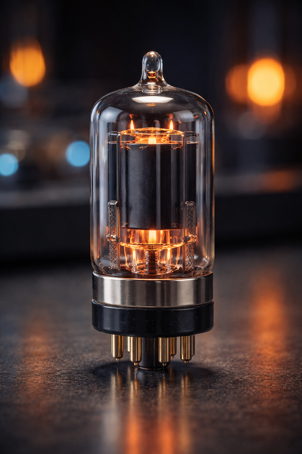
Tube amplifiers, also known as vacuum tube amplifiers, use thermionic valves to increase RF power before it is sent to the antenna. They operate by controlling the flow of electrons through heated vacuum tubes, allowing a small input signal from the transmitter to drive a much larger output signal.
Tube amplifiers like the Ameritron AL 811 can handle high voltage and power levels efficiently, they have long been popular in high-power HF stations. In addition, many operators appreciate their smooth signal characteristics and tolerance of impedance mismatches compared to some solid-state designs.
However, tube amplifiers require proper warm-up time, careful tuning, and adequate cooling, since they generate significant heat during operation. Despite their age, they remain widely used where high output power and rugged performance are important.
Advantages:
- Tolerate impedance mismatch better
- High power capability
- Robust overload handling
Considerations:
- Large size and weight
- High operating voltage
- Warm-up time required
- Periodic tube replacement
Solid-State Amplifiers
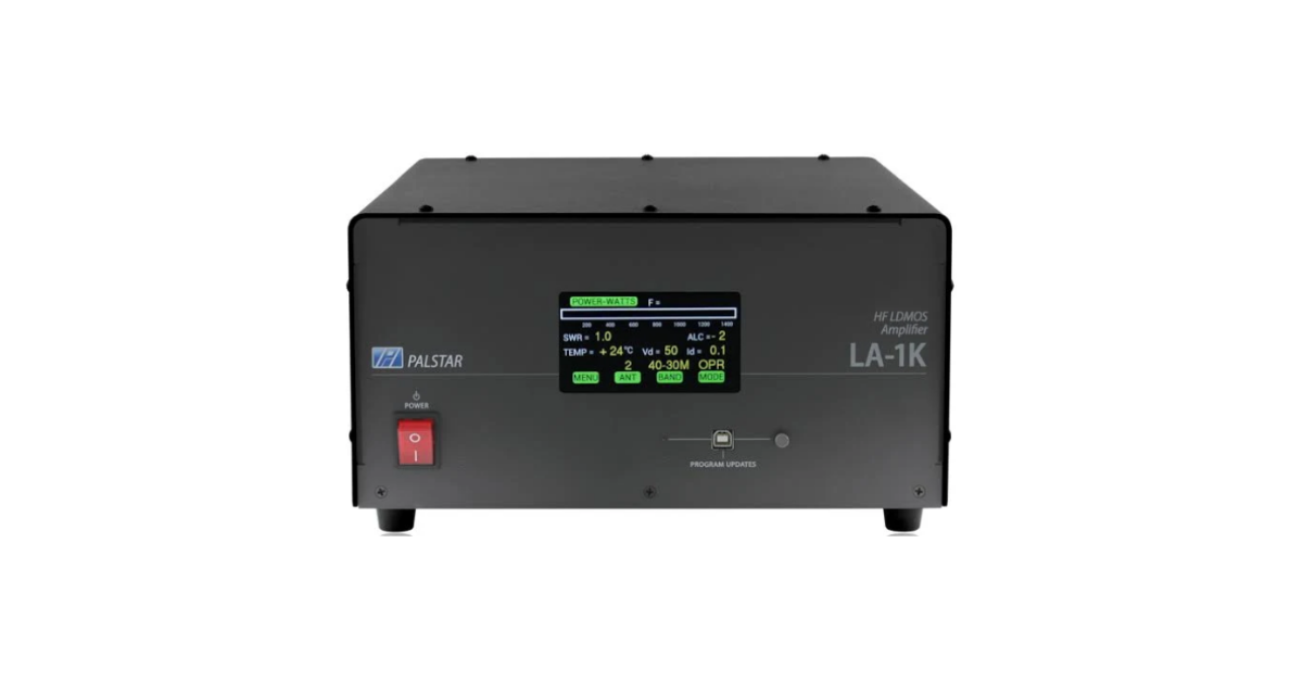
Solid-state amplifiers like the Palstar LA1K use semiconductor devices such as transistors to boost RF power before it is delivered to the antenna. Unlike tube amplifiers, they do not require warm-up time and typically operate with greater electrical efficiency and lower heat output.
As a result, they offer instant-on convenience, compact size, and minimal routine maintenance, which makes them popular in modern ham radio stations. Many solid-state designs also include built-in protection circuits that monitor SWR, temperature, and drive levels to prevent damage.
However, they are generally less tolerant of high impedance mismatches than tube amplifiers, so proper antenna tuning is especially important. Overall, solid-state amplifiers provide reliable, efficient performance with user-friendly operation for everyday and contest use.
Advantages:
- Instant operation
- Compact size
- High efficiency
- Automatic band switching
- Sophisticated protection circuits
Considerations:
- More sensitive to SWR mismatch
- Generally more expensive at very high power
Modern designs increasingly favor solid-state technology due to convenience and reliability.
Amplifier Classes and Efficiency
Amplifier classes describe how an amplifier conducts and processes the RF signal, and they directly affect efficiency, linearity, and signal quality. For example, Class A amplifiers conduct continuously and produce very clean, highly linear signals, but they are inefficient and generate significant heat. In contrast,
Class B and Class AB designs conduct for only part of the signal cycle, improving efficiency while still maintaining good linearity, which makes them common in SSB and other linear operating modes. Meanwhile, Class C amplifiers conduct for less than half the signal cycle, achieving high efficiency but producing more distortion, so they are typically used for continuous-wave and other constant-envelope modes.
As efficiency increases, signal linearity generally decreases, so each amplifier class represents a tradeoff between power consumption, heat generation, and signal fidelity depending on the operating needs.
Class A – highest linearity, lowest efficiency
Class AB – common for linear RF amplification
Class B – improved efficiency, moderate linearity
Class C – high efficiency, not linear (used for CW or FM)
Most SSB and digital operation requires Class AB amplification for clean signal reproduction.
Power Supply Requirements
Amplifier power supply requirements are critical because the power supply must deliver stable voltage and sufficient current to support the amplifier’s output without fluctuation. High-power RF amplifiers, especially tube designs, often require substantial input power and may operate at high voltages, making proper wiring, circuit protection, and grounding essential for safe operation.
In addition, the power supply must handle peak demand during transmission without sagging, since voltage drops can reduce output power and cause distortion. Solid-state amplifiers typically use regulated power supplies for stable performance, while larger systems may require dedicated AC circuits to prevent overloads.
Therefore, matching the power supply capacity to the amplifier’s specifications ensures reliable operation, protects equipment, and maintains consistent signal quality.
- 120V or 240V AC
- High current levels
- Heavy duty wiring
Proper grounding and electrical safety are essential. Many amplifiers include built-in power supplies, while others require external high-voltage units.
Cooling and Thermal Management
Cooling and thermal management are essential for maintaining amplifier performance, reliability, and longevity. As amplifiers operate, they convert electrical energy into RF power, but a significant portion of that energy becomes heat that must be removed to prevent component damage.
Without proper cooling, excessive temperatures can reduce efficiency, distort signals, and shorten the lifespan of transistors or vacuum tubes. Most amplifiers rely on heat sinks, forced-air fans, or even liquid cooling in high-power systems to dissipate heat effectively.
In addition, adequate ventilation around the equipment and regular cleaning of air pathways help maintain proper airflow. By controlling temperature and preventing thermal buildup, effective cooling ensures stable operation and protects your amplifier during extended transmission periods.
Cooling methods include:
- Forced air fans
- Heat sinks
- Thermal sensors
- Automatic shutdown protection
Adequate airflow and operating duty cycle management are critical, especially for digital modes with continuous transmission.
Matching and SWR Protection
Matching and SWR protection are critical for safeguarding an amplifier and ensuring efficient power transfer to the antenna system. When impedance is properly matched, RF energy flows smoothly from the amplifier into the feedline with minimal reflection. However, if SWR rises due to antenna problems, feedline faults, or operation outside the antenna’s designed frequency range, reflected power can return to the amplifier and cause overheating, distortion, or component failure.
To prevent this, many modern amplifiers include built-in protection circuits that monitor SWR and automatically reduce output power or shut down if unsafe conditions occur. Even with these safeguards, proper antenna tuning and system matching remain essential, because maintaining low SWR not only protects equipment but also maximizes transmitted signal strength and overall station efficiency.
Modern amplifiers often include:
- SWR monitoring
- Automatic foldback power reduction
- Shutdown protection
- Fault indicators
Proper antenna tuning remains essential for safe operation.
Legal Power Limits
Amateur radio regulations define maximum transmitter power levels. Operators must ensure amplifier output remains within legal limits for their license class and operating region.
Excessive power can cause interference, equipment stress, and regulatory violations
When You Should Use an Amplifier
Amplifiers are most beneficial when:
- Working long-distance HF contacts
- Operating during poor propagation
- Contesting or pileup situations
- Weak-signal communication
- Emergency communication reliability
However, better antennas, height, and propagation timing often produce greater improvement than additional power alone.
Safe Operating Practices
Always:
- Monitor output power and SWR
- Ensure adequate ventilation
- Use proper grounding
- Follow duty cycle limits
- Verify legal compliance
Responsible operation protects equipment and preserves signal quality for other operators.
Complete Guide to Ham Radio Amplifiers
Complete Guide to Ham Radio Amplifiers, they extend communication capability by increasing transmitted signal strength, but they also introduce technical complexity and responsibility. Understanding amplifier types, operating principles, power requirements, and system integration ensures reliable performance and clean transmissions.
When properly selected, installed, and operated, an amplifier becomes a powerful tool that enhances station capability and expands communication range across the amateur radio spectrum.
Please consider Donating to help support this channel