
The Standing Wave Ratio (SWR) is a crucial parameter in the field of radio frequency (RF) engineering, particularly concerning antennas and transmission lines. It is a measure of how well an antenna system matches the impedance of the transmission line to the impedance of the transceiver, however, understanding the concept of SWR is essential for optimizing antenna performance and minimizing signal loss.
A good SWR for amateur radio is typically 1.5:1 or lower, with 1.0–1.3:1 considered ideal. Most modern transceivers can safely operate with SWR values up to 2:1, but higher ratios indicate inefficient power transfer and potential equipment stress. Understanding SWR helps radio operators tune antennas for maximum signal strength and transmitter protection.
What Is a Good SWR for Amateur Radio
A good SWR for amateur radio is typically 1.5:1 or lower, with 1.0–1.3:1 considered ideal. Most modern transmitters can safely operate with SWR values up to 2:1, but higher ratios indicate increasing power reflection and reduced antenna efficiency.
Operators generally aim for the lowest SWR possible at their operating frequency to ensure maximum power transfer and equipment protection.
What Is a Good SWR for Amateur Radio?
Explain real-world acceptable ranges:
- 1.0–1.3 ideal
- 1.5 excellent
- 2.0 usable
- 3.0+ dangerous
Impedance Matching:
Impedance is a measure of opposition to the flow of alternating current (AC) in a circuit. In the context of antennas, however, impedance matching ensures that the antenna’s impedance closely matches the impedance of the transmission line (which is usually 50 ohms for most radio systems.)
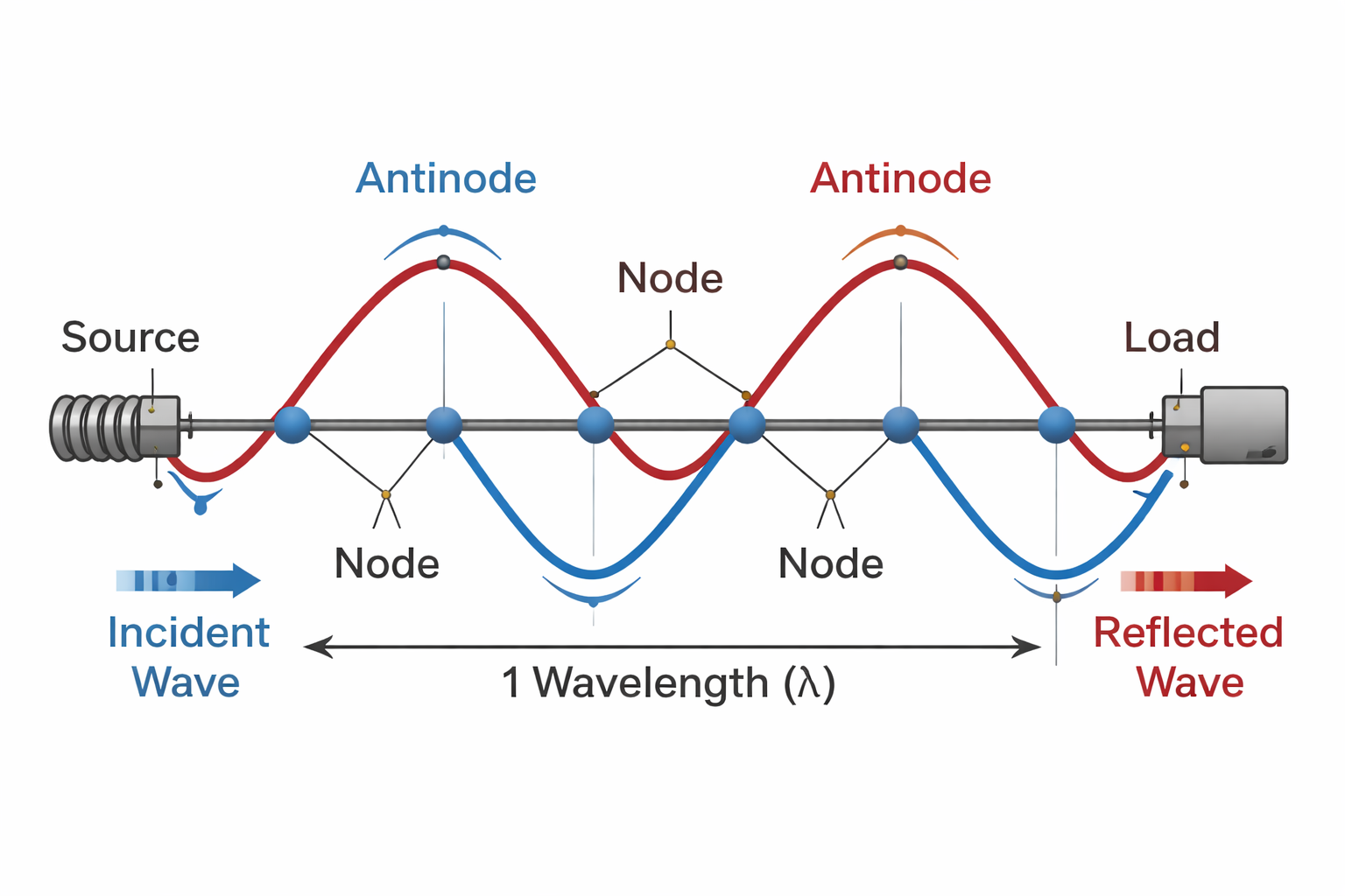
Reflection and Standing Waves:
If there is a mismatch between the antenna and the impedance of the transmission line. As a result, part of the energy sent by the transmitter is reflected back towards the source. This reflection creates standing waves along the transmission line. The incoming and reflected waves interfere with the standing waves.
Standing Wave Ratio (SWR):
The SWR is a numerical representation of the efficiency of power transfer between the transmitter and the antenna system. It is defined as the ratio of the maximum radio frequency (RF) voltage (or current) in the transmission line to the minimum RF voltage (or current) in the same line. The SWR is mathematically, expressed as:
A perfectly matched system, for example, where the antenna impedance equals the transmission line impedance, would result in an standing wave ratio of 1:1. In practical scenarios, an SWR of 1:1 is ideal, indicating minimal reflection and maximum power transfer.
Interpreting SWR Values:
SWR values are typically represented as a ratio, such as 1:1, 1.5:1, 2:1, etc. Here’s how to interpret these values:
- SWR = 1:1: Perfect match. Indicates a perfect impedance match between the transmitter and transmission line, and no power is reflected back towards the transmitter.
- SWR < 1.5:1: Excellent match. Indicates minimal reflected back, and the system operating efficiently.
- SWR = 2:1: Acceptable match. While not ideal, most transmitters can handle an SWR of 2:1 without significant issues.
- SWR > 2:1: Mismatch. The transmitter has significant power reflected back. Potentially causing damage and reducing efficiency.
SWR Power Loss and Reflected Power Chart
| SWR Ratio | Reflected Power | Power to Antenna | Signal Loss (Approx) |
|---|---|---|---|
| 1.0 : 1 | 0% | 100% | 0 dB |
| 1.2 : 1 | 0.8% | 99.2% | Negligible |
| 1.5 : 1 | 4% | 96% | Very small |
| 2.0 : 1 | 11% | 89% | Minor |
| 2.5 : 1 | 18% | 82% | Noticeable |
| 3.0 : 1 | 25% | 75% | Significant |
| 5.0 : 1 | 44% | 56% | Severe |
| 10 : 1 | 67% | 33% | Extreme |
Bandwidth and Frequency Range
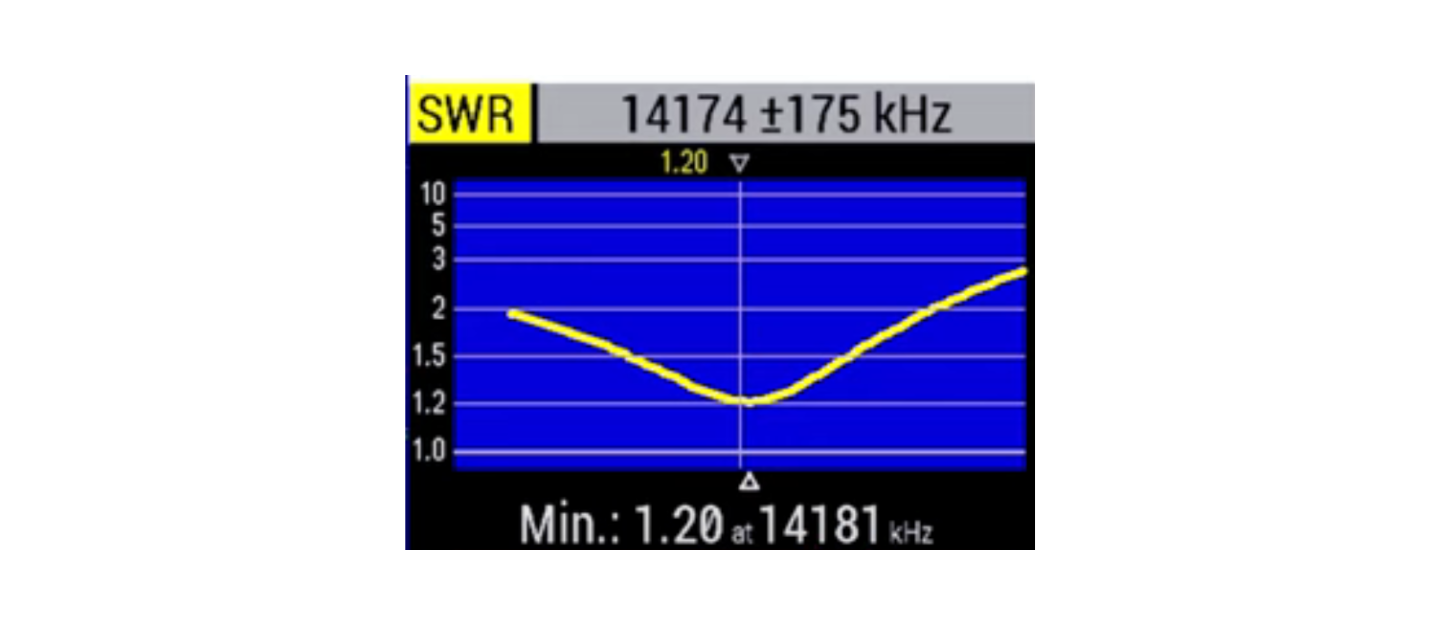
SWR does not remain constant across an entire amateur radio band. Most antennas are resonant at a specific frequency where the SWR is lowest. As the operating frequency moves away from resonance, the SWR gradually increases.
This usable frequency range is called the antenna bandwidth.
For example, a dipole antenna tuned for 14.200 MHz may show:
• 1.2:1 SWR at 14.200 MHz
• 1.5:1 SWR at 14.100 MHz
• 2.0:1 SWR near the band edges
Understanding bandwidth helps operators design antennas that perform well across the entire band rather than only at one frequency.
Importance of SWR:
Maintaining a low SWR is crucial for several reasons:
- Efficiency: A low SWR ensures efficient power transfer between the transmitter and the antenna, resulting in better signal propagation.
- Equipment Protection: High SWR values can cause excessive heat and stress on transmitters, potentially damaging the equipment.
- Signal Quality: A well-matched system enhances the quality of transmitted and received signals by reducing interference.
Measurement and Adjustment:
Standing wave ratio is typically measured using an SWR meter. Adjustments to the antenna or transmission line length can be made to achieve a lower SWR. Matching the impedance and minimizing reflected power can be achieved with an antenna analyzer.
Understanding and monitoring the Standing Wave Ratio of an antenna system is essential for maintaining efficient communication in radio frequency applications. A well-matched system ensures optimal power transfer and minimizes the risk of equipment damage, contributing to a reliable and effective radio communication setup.
Tuning an antenna for the lowest Standing Wave Ratio (SWR) is a critical step in optimizing your radio frequency (RF) system for efficient signal transmission.
For more detailed testing, many operators use an antenna analyzer to measure impedance and resonance across the band.
Equipment Needed:
- SWR meter: Use a quality SWR meter to measure the SWR of your antenna system.
- Coaxial Jumper Cable: Ensure you have a good-quality coaxial jumper cable for connecting your transmitter, SWR Meter, to the antenna.
- Adjustable antenna: If your antenna is tunable, make sure it has the necessary adjustment mechanisms. You can tune wire antenna by adding or shortening the wires equally.
Tuning the Standing Wave Ratio:
- Choose a Clear Frequency: Select the desired frequency and make sure it is clear frequency.
- Connect SWR Meter: Connect the SWR meter in line with your transmitter and antenna, or use an antenna analyzer. The SWR meter typically has two connectors: one for the transmitter, and one for the antenna.
- Set Transmitter to Low Power: Set your transmitter to low power (usually 10 watts or less) to avoid damaging the radio or SWR meter.
- Check Baseline SWR: With the SWR meter connected, key the transmitter and check the baseline SWR reading.
- Adjust Antenna Length: If the SWR reading is high, it indicates a mismatch between the antenna and the transmission line. Adjust the length of the antenna elements slightly to find the lowest SWR. When the SWR is high you need to lengthen the antenna. If the SWR is low, you will need to shorten the antenna.
- Check SWR Again: Key the transmitter again and observe the SWR reading on the meter. Repeat the process if needed for the lowest SWR. This may take many adjustments, or if you are lucky, just a few.
Matching Networks:
- Adjust Matching Network (If Applicable): Some antennas come with built-in matching networks or tuners. If your antenna has this feature, you can use it to fine-tune the impedance match. Follow the manufacturer’s instructions for adjusting the matching network.
- Reconnect at Full Power: After reaching the lowest SWR at low power. Increase the transmitter to full power and check the SWR again. This ensures that the SWR remains low at higher power levels.
- Verify Across the Band: Check the SWR across the entire frequency band you plan to use.
- Secure Connections: After achieving the desired SWR, ensure that all connections are secure. Loose connections can lead to changes in the SWR over time.
- Repeat if Necessary: If you make significant changes to your antenna system or relocate it, it’s a good practice to check and retune the antenna for the lowest SWR again.
Make small adjustments, and take your time to achieve the best standing wave ratio. Additionally, be careful not to cut the antenna to short. Patience is the key to a finely tuned antenna.
Adding an inline a SWR/Power meter to monitor your SWR is essential for ensuring optimal performance of your radio equipment. This versatile device allows you to measure the Standing Wave Ratio (SWR) and output power of your transmitter, in addition to, alerting you to any possible issues. Here’s a brief guide on how to get and use a SWR/Power meter effectively:
Monitor the Standing Wave Ratio with an SWR/Power Meter:
- Choose the Right Meter: There are various types and models of SWR/Power meters available on the market, ranging from basic analog meters to sophisticated digital models. Consider your budget, frequency range, and features required before making a purchase.
- Quality Matters: Invest in a quality SWR/Power meter from a reputable manufacturer. A reliable meter will provide accurate measurements and withstand the rigors of regular use. This meter will protect thousands of dollars worth of gear, so this is not an area to try and save money.
- Check Compatibility: Ensure that the SWR/Power meter you choose is compatible with your radio equipment and operating frequency range. Some meters are designed for specific bands or transmission power levels.
Using a SWR/Power Meter:
- Connect the Meter: Connect the SWR/Power meter between your transmitter and antenna using a high quality coaxial cable jumper. Follow the manufacturer’s instructions for proper connection.
- Set Power Level: Set your transmitter to a low power level (usually 10 watts or less) to avoid damaging the meter during the measurement process. Consult your radio manual for instructions on adjusting power output.
- Calibrate the Meter: Before taking measurements, ensure that the SWR/Power meter is properly calibrated. Follow the calibration procedure outlined in the meter’s user manual to ensure accurate readings. New meter usually come calibrated these days.
- Measure SWR: Key the transmitter and observe the SWR reading on the meter’s display. Monitor the SWR during operation because this can alert you to problems as they arise.
- Measure Power Output: In addition to SWR, the SWR/Power meter also measures the output power of your transmitter. This allows you to ensure that your transmitter is operating within its specified power range. It also keeps you from overdriving an amplifier.
Step-by-Step Procedure for Tuning SWR
Begin by measuring the current SWR at your operating frequency. Always take readings at low transmit power to protect equipment during adjustment.
Next, identify whether the antenna is electrically too long or too short by checking SWR across nearby frequencies. If SWR improves at higher frequencies, the antenna is too long. If SWR improves at lower frequencies, the antenna is too short.
Adjust antenna length gradually. Small physical changes can produce significant electrical effects, especially on higher frequencies.
After each adjustment, measure SWR again and compare results. Continue making small corrections until the lowest possible SWR occurs at the desired operating frequency.
Finally, verify system performance across the entire operating band. Some antennas tune narrowly, while others provide wider usable bandwidth.
Real-World Example of SWR Adjustment
Consider a dipole antenna designed for 14.200 MHz on the 20-meter band. After installation, the antenna measures an SWR of 2.5:1 at the desired frequency.
Testing shows the SWR improves at slightly higher frequencies, indicating the antenna is electrically too long.
By shortening each element by about one inch and rechecking the measurement, the SWR drops to 1.4:1 at the target frequency.
This small adjustment significantly improves power transfer and ensures the transmitter operates efficiently.
Common Causes of High SWR
High SWR often results from incorrect antenna length, poor grounding, or feedline damage. Loose connectors and water intrusion frequently create impedance mismatch.
Nearby metal objects can detune antennas significantly. Even small environmental changes can affect resonance. Using the wrong feedline impedance or damaged coax also produces high reflection levels. Systematic inspection of the entire signal path usually reveals the cause quickly.
Proper grounding is also important for many antenna systems and can significantly affect SWR and radiation efficiency.
SWR Troubleshooting Guide
Common problems that cause high SWR include:
• Incorrect antenna length
• damaged coax cable
• poor grounding
• loose connectors
• water in feedline
• nearby metal objects
• incorrect feedline impedance
What Experienced Operators Know About SWR
Low SWR alone does not guarantee efficient radiation. A system may show acceptable SWR while losing significant power in the feedline. Impedance matching at the antenna feedpoint improves efficiency more than matching inside the shack.
Serious operators evaluate SWR together with impedance, feedline loss, and radiation performance to achieve the strongest real signal. Understanding the complete RF system produces better results than focusing on meter readings alone.
Practical SWR Insights from Experienced Operators
Many experienced amateur radio operators learn that chasing a perfect 1:1 SWR is not always necessary. In real-world operating conditions, an SWR of 1.5:1 or even 2:1 can perform extremely well.
What matters most is overall antenna efficiency and radiation performance.
Operators often evaluate:
• feedline loss
• antenna height above ground
• antenna radiation pattern
• surrounding environment
• impedance at the antenna feedpoint
A system with slightly higher SWR but excellent antenna placement may produce a much stronger signal than a perfectly matched antenna located in a poor position.
My Standing wave Ratio Meters:
A SWR/Power meter is an invaluable tool for any radio operator, providing essential measurements to optimize antenna performance and ensure efficient signal transmission. By following the steps outlined above and using your SWR/Power meter effectively, you can maximize the performance of your RF system and enjoy clear and reliable communications.
I use the Telepost LP-100A digital watt meter/SWR that has many other features after my amplifier. There are various couplers that cover HF and NHF/UHF and different power levels. The LP-100A can use 1 or 2 couplers. At a 500 to 600.00 price with one coupler it can be expensive, however, it is so accurate that major companies use it. It offers all the signal parameters at once, and has a computer interface for even more features
Also, a good alternative is the Nissei DG-503, It cover 1.8 to 60MHz plus VHF/UHF. This was my first meter and I still use it before my amplifier. This has a 200 watt power limit and digital readout with backlight. I loved the large 3.5″ display screen and then controls were easy to understand. It has a high accuracy: (AVG) +/- 5% & Low insertion loss: < 0.3dB The connections are easy understand, but always read the manual first for any tips.

Final Thoughts
Standing Wave Ratio is one of the most important measurements in amateur radio antenna systems. Maintaining a low SWR improves power transfer, protects radio equipment, and ensures efficient signal radiation.
By understanding impedance matching, measuring SWR accurately, and adjusting antenna length carefully, radio operators can achieve reliable communication and strong transmitted signals.
Even small improvements in antenna tuning can produce noticeable improvements in station performance.
FAQ
What is a good SWR reading?
An SWR of 1:1 is ideal, but anything below about 1.5:1 is considered excellent for most amateur radio operation.
What happens if SWR is too high?
High SWR causes transmitted power to reflect back toward the transmitter instead of radiating from the antenna. This reduces efficiency and can damage radio equipment if severe.
Can you transmit with high SWR?
Yes, but performance decreases and equipment stress increases. Many modern radios automatically reduce output power when SWR becomes excessive.
Does low SWR mean the antenna is working perfectly?
Not always. Low SWR means good impedance matching, but it does not guarantee maximum radiation efficiency. Feedline loss and antenna design still affect performance.
How do you lower SWR?
SWR is lowered by adjusting antenna length, improving grounding, correcting feedline issues, or using an antenna tuner to match impedance.
About the Author
Vince, W2KU, is a licensed Extra class amateur radio operator and the founder of Ham Shack Reviews. The organization named him Amateur of the Year in 2026 for his contributions to practical amateur radio education and equipment evaluation.
He primarily operates HF, knows propagation very well, operates mobile and handhelds daily. Vince exchanges QSL cards for DXCC, contest confirmation, and award tracking and is the club QSL manager. His guidance focuses on practical operating procedures, accurate logging, and real-world amateur radio practices.