

The end-fed half-wave antenna, usually called the EFHW, has earned a strong reputation among amateur radio operators because it offers an unusual combination of simplicity, portability, multi-band capability, and excellent real-world performance.
Many operators choose this antenna because it requires less physical infrastructure than a traditional center-fed dipole while still delivering reliable communication across multiple HF bands. However, despite its popularity, the EFHW remains one of the most misunderstood antenna designs in amateur radio.
At first glance, the design appears deceptively simple. Many hams see a single wire connected to a small transformer box and assume the antenna is electrically straightforward. In reality, the EFHW depends on careful impedance transformation, feedline management, common-mode current control, and correct installation geometry.
If you ignore those factors, the antenna may still radiate, but performance can suffer badly. Operators often experience unstable SWR, RF feedback in the shack, excessive received noise, and poor radiation efficiency when they treat the EFHW as a simple random wire.
A properly built EFHW, however, can perform remarkably well. It can provide excellent DX capability, effective portable deployment, and dependable multi-band operation while occupying far less space than many alternative HF antennas. Understanding how the system works is the difference between frustration and a highly effective station.
New to antenna systems? See our Complete Guide to Ham Radio Antennas.
What an End-Fed Half-Wave Antenna Actually Is
An end-fed half-wave antenna is exactly what the name suggests: a wire antenna approximately one-half wavelength long for the desired operating frequency, fed from one end instead of from the center. That feed arrangement creates the defining electrical behavior of the antenna.
A traditional dipole receives power at its center, where the feedpoint impedance remains relatively manageable. Because current reaches its maximum near the center of a resonant half-wave conductor, the feedpoint typically falls within a range that matches coaxial cable reasonably well, often around 50 to 75 ohms depending on height, surrounding objects, and installation details.
The End-Fed Half-Wave works very differently because it places the feedpoint at the extreme end of the resonant wire. At resonance, a half-wave conductor exhibits a current maximum near the center and voltage maxima near the ends. That means the end of the wire presents extremely high impedance compared to the center.
Instead of seeing something close to 50 ohms, the feedpoint impedance at the end of a resonant half-wave wire often reaches into the thousands of ohms. Values commonly fall somewhere between 2,000 and 4,000 ohms, although installation conditions can shift those numbers significantly. Since modern amateur transceivers expect approximately 50 ohms, a direct connection between the wire and coax would create a severe mismatch.
That electrical reality explains why the EFHW always requires some form of impedance transformation.
Why the EFHW Needs Impedance Transformation
Efficient RF power transfer depends on matching impedance between the transmitter, feedline, and antenna system. When those impedances differ dramatically, reflected power increases, transmission efficiency falls, and the radio may reduce output to protect itself.
Consider a practical example. If the antenna feedpoint impedance measures approximately 2,450 ohms and the radio expects 50 ohms, the mismatch becomes enormous. Connecting that directly would produce extremely high standing wave ratio and poor system performance. This is where the matching transformer becomes essential.
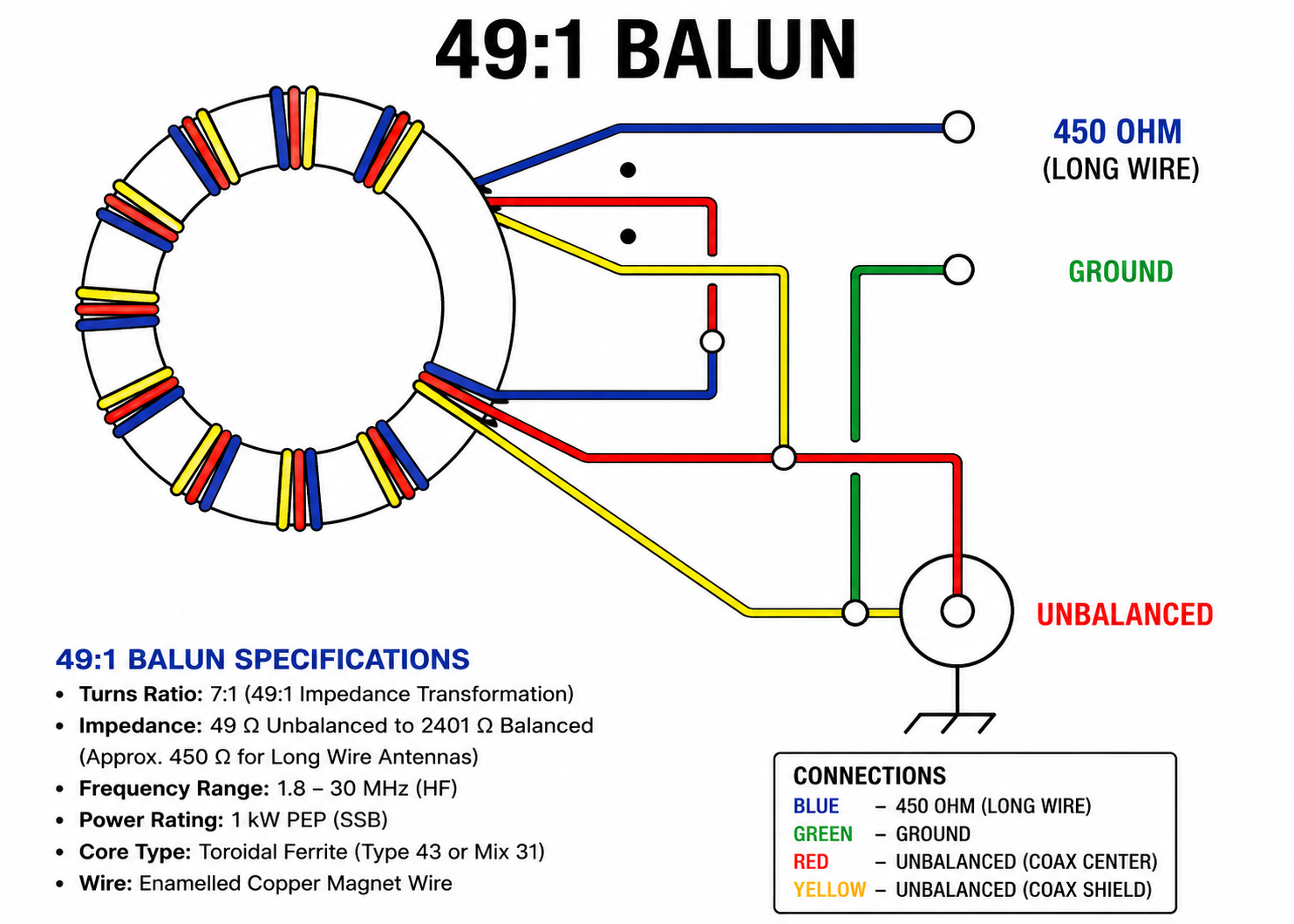
A transformer that converts approximately 2,450 ohms down to 50 ohms solves the problem. The most common ratio used for this purpose is 49:1, which comes from the mathematical relationship between turns ratio and impedance transformation.
Since impedance transformation equals the square of the turns ratio, a 1:7 turns ratio produces a 49:1 impedance transformation. This means the transformer does not magically make the antenna resonant. Instead, it translates the high feedpoint impedance into something the radio and coax can handle efficiently.
That distinction matters because many operators misunderstand the transformer’s role. The transformer does not fix a badly cut antenna. It does not compensate for poor installation geometry. It does not eliminate common-mode current problems, it simply performs impedance transformation.
Understanding Ununs and Baluns in EFHW Systems
One of the most persistent sources of confusion surrounding End-Fed Half-Wave antennas involves the difference between a balun and an unun. Amateur radio discussions frequently blur these terms, yet the distinction matters when building an effective antenna system.
A balun is a balanced-to-unbalanced device. The word itself comes from that exact phrase. A balanced antenna carries equal and opposite currents on two conductors, as seen in a center-fed dipole. Coaxial cable, by contrast, is unbalanced because the center conductor and shield do not behave symmetrically.
A balun connects balanced antennas to unbalanced feedlines. An unun, on the other hand, means unbalanced-to-unbalanced. It connects an unbalanced load to an unbalanced feedline while providing impedance transformation.
Because an EFHW uses a single wire rather than a balanced pair of conductors, it is fundamentally an unbalanced antenna. That means the transformer at the antenna feedpoint is technically an unun, not a balun. However, the story does not end there.
Why a Balun May Still Be Needed
Although the EFHW uses an unun for impedance matching, many installations still require a current balun or choke balun elsewhere in the system. This is where newer operators often become confused. The reason involves common-mode current.
In an ideal antenna system, RF current flows exactly where the design intends. In real installations, the antenna still needs a return path. If that return path is not intentionally controlled, RF often travels along the outside of the coax shield. When that happens, the feedline becomes part of the antenna.
This creates several familiar problems. SWR may change when the coax moves. RF may enter microphones, computers, or audio equipment. Radiation patterns may become distorted. Noise pickup may increase dramatically. The station may behave unpredictably.
A current choke solves that issue by presenting high impedance to unwanted common-mode current while allowing desired differential RF current to pass normally. So the correct EFHW arrangement often includes both devices: an unun at the feedpoint for impedance transformation and a choke balun for feedline current suppression.
Choosing Between 49:1 and 64:1 Transformers
The 49:1 transformer remains the most common solution for EFHW antennas because many resonant half-wave installations present feedpoint impedances near the range that ratio handles effectively.
A 49:1 transformer works well for the majority of common amateur HF EFHW designs, especially when building antennas for 40, 20, or 80 meter operation with harmonic multi-band use.
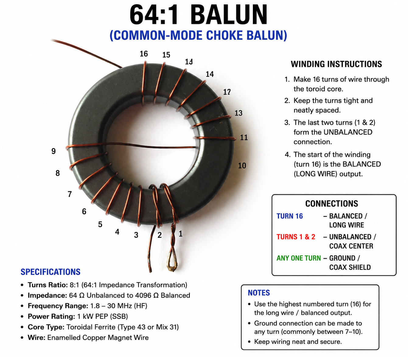
However, some installations behave differently. Feedpoint impedance can vary due to wire height, nearby conductive structures, environmental coupling, and antenna geometry. In some cases, a 64:1 transformer may produce a better match.
A 64:1 transformation comes from an 8:1 turns ratio. That configuration handles higher impedance loads more effectively.
Still, most builders begin with 49:1 because it has proven effective across a wide range of real-world installations. Unless testing suggests otherwise, it remains the practical starting point.
Ferrite Core Selection for the Transformer
Ferrite core choice significantly affects transformer efficiency, thermal performance, and reliability. Many poorly performing EFHW transformers fail not because the concept is flawed, but because the builder selected inadequate materials.
The core must handle the intended frequency range and power level without excessive loss or saturation. HF operators commonly use ferrite mixes such as 43, 52, and 61, though mix 43 remains especially popular for general HF EFHW applications.
For low-power portable use, smaller cores may suffice. However, fixed stations operating 100 watts or digital modes require larger cores with better thermal margin.
Digital modes deserve special caution because they create sustained duty cycles far higher than voice operation. SSB voice produces intermittent peaks, while modes such as FT8 or RTTY can maintain near-continuous RF output. A transformer that survives casual voice operation may overheat badly during digital use.
A single FT-240-43 core works well for many 100-watt applications. Higher duty cycles or greater power often justify stacked cores for improved heat handling and reduced losses.
Building the EFHW Matching Transformer
The most common EFHW transformer uses an autotransformer winding arrangement. While designs vary, the typical 49:1 transformer uses a 1:7 turns ratio.
That ratio means the primary section uses fewer turns while the full winding provides the secondary transformation. Because impedance transformation follows the square of turns ratio, seven squared yields forty-nine. A practical build typically includes a ferrite toroid, insulated wire, connector hardware, antenna terminal hardware, and an enclosure suitable for outdoor use.
Wire gauge matters. Thicker wire handles higher power and mechanical stress better, while thinner wire becomes easier to wind on smaller cores. Many builders prefer PTFE-insulated wire because it handles heat well and remains durable under outdoor temperature variation.
Winding layout also matters. Sloppy construction increases parasitic coupling, introduces unpredictable capacitance, and reduces consistency. Careful spacing improves repeatability.
Some designs also include a high-voltage capacitor across part of the winding to improve high-frequency performance. Because the EFHW feedpoint can develop substantial RF voltage, component voltage ratings must remain generous.
Weatherproof Enclosure Selection
Outdoor reliability depends heavily on enclosure quality. The matching transformer lives in one of the harshest parts of the antenna system because it experiences temperature swings, moisture, UV exposure, and mechanical stress from the antenna wire itself.
Cheap hobby project boxes often fail quickly. Thin plastic becomes brittle under sunlight, seals deteriorate, and mounting points crack under wire tension.
A far better approach uses UV-resistant outdoor-rated electrical enclosures. Polycarbonate junction boxes perform especially well because they combine durability, weather resistance, and mechanical strength. Fiberglass enclosures also work well for permanent installations.
The enclosure should never carry full antenna tension through electrical terminals. Instead, mechanical strain relief should transfer load to dedicated hardware. Cable glands improve sealing while preventing moisture intrusion around coax entry points.
Choosing the Right Antenna Wire
Wire selection influences both electrical performance and physical durability. Electrically, many wire types perform similarly enough that installation quality matters more than exotic conductor choices. Mechanically, however, differences become significant.
Stranded copper wire offers flexibility and easy handling. Copper-clad steel provides much greater tensile strength, which helps in permanent outdoor installations where wind loading matters. Insulated wire changes electrical length slightly because the dielectric affects velocity factor.
Portable operators often favor lighter wire for reduced weight, while fixed installations benefit from heavier conductors that survive environmental stress more effectively. For most permanent EFHW antennas, 14 to 16 AWG provides an excellent balance between strength and ease of use. Heavier gauges improve durability, though they also increase weight and visual impact.
Calculating Wire Length
The starting point for a half-wave wire calculation uses the familiar formula: = 468 divided by frequency in megahertz. For example, a 40 meter EFHW centered near 7.15 MHz calculates as approximately 65.5 feet. That value serves only as a starting point.
Real installations almost always require trimming because surrounding conditions alter effective electrical length. Wire insulation, mounting height, nearby metal, transformer capacitance, and routing geometry all shift resonance.
For that reason, builders should always cut long and trim downward gradually. Common starting points include approximately 66 feet for a 40 meter EFHW and roughly 130 feet for an 80 meter version. However, final dimensions depend entirely on the actual installation. You can use our End Fed wire calculator for exact measurements of all bands.
Multi-Band Operation
One of the EFHW’s biggest attractions is harmonic operation. A resonant half-wave wire often supports harmonic frequencies naturally. A 40 meter EFHW commonly performs on 20, 15, and 10 meters. An 80 meter version often supports multiple higher harmonic bands.
This makes the antenna extremely attractive for operators seeking broad band coverage from a single wire. However, not every band behaves equally well. Installation geometry, transformer characteristics, and common-mode behavior all affect actual performance.
Therefore, while multi-band operation remains a major strength, expectations should remain grounded in testing rather than assumption.
Mounting the Antenna for Best Performance
Physical installation dramatically shapes real-world results. A horizontal configuration often produces behavior closest to a traditional dipole pattern when sufficient height exists. This arrangement can perform exceptionally well for DX and general HF operation.
A sloper remains one of the most popular configurations because it requires only one high support. It works well in many suburban environments and portable deployments.
An inverted-L helps where horizontal space is limited, especially on lower bands where full horizontal deployment becomes impractical.
Height matters significantly. Raising the antenna generally improves efficiency and pattern behavior, particularly on lower HF bands. A poorly installed high-quality EFHW will often underperform a simpler antenna installed well.
Coax Selection
Feedline loss becomes increasingly important as frequency rises and cable length increases. Short portable runs may work acceptably with smaller coax, but permanent installations benefit from lower-loss cable.
RG-8X offers a practical balance between flexibility and performance for many stations. LMR 400 provides stronger durability and lower loss, making it attractive for permanent installations. Higher-performance low-loss coax becomes especially valuable when feedline runs grow long.
Because the EFHW can involve feedline interaction, coax routing also matters. Sharp bends, routing near conductive structures, and proximity to household wiring can influence behavior.
Tuning the EFHW
Tuning should occur only after final installation. Testing the antenna on the ground and expecting identical installed performance leads to frustration because height and surroundings strongly affect resonance.
An antenna analyzer simplifies tuning dramatically. Install the antenna at intended height, route the coax as planned, and then measure resonance.
If resonance falls below the desired operating frequency, shorten the wire gradually. If resonance falls above the target, the wire needs lengthening, which is why starting long matters. Small adjustments can produce meaningful frequency shifts, especially on higher bands.
Troubleshooting Common Problems
If SWR remains high across all bands, transformer construction should become the first suspect. Incorrect turns ratio, wrong tap points, poor solder joints, or faulty connectors frequently cause this issue.
If SWR appears acceptable but performance disappoints, common-mode current may be distorting the system. A properly placed choke often improves stability dramatically.
If RF enters the shack, the coax shield almost certainly participates in unintended radiation. That problem requires feedline current suppression rather than endless tuning adjustments. When transformer heating occurs, the core likely lacks adequate thermal margin for the power level or operating mode.
Final Thoughts on The End-Fed Half-Wave
The end-fed half-wave antenna deserves its popularity, but only when operators understand what the design actually requires. It is not a magical wire that works perfectly regardless of installation details. It is a legitimate and capable antenna system that depends on correct engineering choices.
When built properly, the EFHW offers impressive versatility, strong multi-band capability, easy deployment, and excellent operating performance. When built carelessly, it becomes noisy, unstable, and frustrating. Success comes from respecting the electrical realities behind the design.
Please consider Donating to help support this channel