
Making a K4 to la1k interface cable is not hard if you know the basics. It is just connecting the right wires to the right places and there only 6 of them for this set up. The first step is to get the parts you will need for this little project.
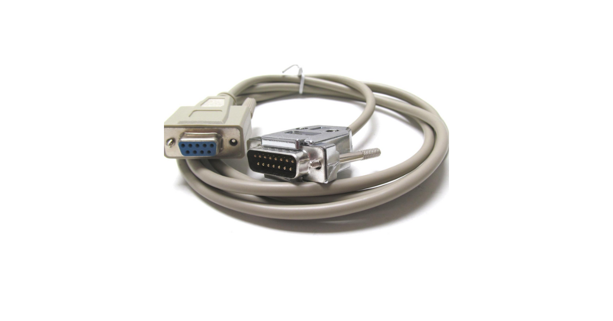
The male DB-9 connector with cable is a fundamental component in the realm of electronics and computer hardware. This connector, also known as a D-subminiature or D-sub connector, is widely used for serial communication, data transmission, and various other applications. Here’s a review of the male DB-9 connector with cable, highlighting its features, performance, and overall value:
The male DB-9 connector typically features a sturdy metal shell with nine pins arranged in a rectangular pattern. The connector’s construction is robust and durable, ensuring long-term reliability and performance. The cable attached to the connector is usually made of high-quality materials, such as shielded copper wires, to provide excellent signal integrity and protection against electromagnetic interference (EMI).
Features:
- Standard Connectivity: The DB-9 connector follows a standardized pinout configuration, making it compatible with a wide range of devices and equipment that utilize serial communication protocols.
- Versatility: This connector is versatile and can be used in various applications, including computer peripherals, industrial machinery, networking equipment, and more.
- Easy Installation: The connector’s design allows for easy installation and connection to compatible devices, with clearly labeled pins for straightforward wiring.
The 3-row DB-15 connector with screw terminals is a versatile and practical solution for various electronics and connectivity applications. Designed to accommodate multiple signal lines in a compact form factor, this connector offers convenience, flexibility, and ease of installation. Here’s a detailed review highlighting its features, performance, and overall value:
The DB-15 connector features a durable plastic housing with three rows of screw terminals, allowing for easy termination of wires without the need for soldering. The screw terminals provide a secure and reliable connection, ensuring minimal signal loss and optimal conductivity. The connector’s compact design makes it suitable for use in tight spaces and crowed environments, while its sturdy construction ensures durability and longevity.

Features:
- Versatile Connectivity: The DB-15 connector is compatible with a wide range of devices and equipment, offering versatile connectivity options for audio, video, and data signals.
- Screw Terminals: The screw terminals allow for quick and convenient termination of wires, enabling easy installation and maintenance without the need for specialized tools or soldering equipment.
- Compact Form Factor: The connector’s compact size makes it ideal for space-constrained applications, such as rack-mounted equipment, industrial machinery, and control panels.
The K4 uses a DB15/DE15 male connector. I use the breadboard type with screw terminals, this removes the soldering and is easier to make changes. The image above shows the 4 pack of DB15 connectors which gave me two males and two females. I like having parts on hand when I need them.
Make sure you order a long enough cable. Both the K4 and LA1K are also compatible with Kenwood’s interface connections but a male DB9 with wire would be needed for those connections. I believe there are only 3 wire connection with the Kenwood set up.


You will need to pull these two wiring diagrams from the manuals of the K4 and LA1K. They will show the wire connections of the radio and amp.
Interface Cable Pin Out

The information needed to make the cable is on the diagram above. The upper left shows the wire connection. The writing in red shows the data from the two manuals. All data cables use these codes.
The DB9 connector with cable I ordered did not have the wire ends marked so I had to trace them with a multi meter. If you purchase the same cable here, the wire colors and above chart will work without having to trace them.
The Band
- Pin 13 goes to Pin 2
- Pin 3 goes to Pin 1
- Pin 9 goes to Pin 9
- Pin 14 goes to Pin 8
The keying circuit needs ground wire to work. The DB15 has two of them on Pin 5 and Pin 12 while the DB9 has one on pin 6. I used pin 12 because of tis location in the connector.
- Pin 12 goes to Pin 6
Keying the amplifier can be done two ways, It can be keyed through the interface cab le or by using the RCA phone jacks. If you use an automatic antenna tuner you will want to use the RCA phono jacks. The tuner will delay the amplifier from keying until the tuner finishes.
If you use a manual antenna tuner like I do, you can have the interface cable handle the keying. Make the connection below:
- Pin 10 goes to Pin 7
K4 to LA1K Interface Cable
This will finish the cable connections, so you can close up the DB15 connector and give it a try. Once the cable is together, connect the DB 15 to the Elecraft K4 using acc. jack. The DB 9 will connect to the Palstar LA1K with the Yaesu jack. If you used the RCA phono jacks for keying you will want to connect them now.
When first testing the cable, keep the amplifier in stand by mode and try all the bands to ensure they change properly. Then put the amplifier in operate mode, and see if it keys the amp correctly. Try this on low power to ensure it keys correctly.
ALC Connections
If you use the ALC to keep the amp from over driving by accident, you can follow the instruction from Palstar. I know there are specific instructions on making this work.
Get on the air and make some contacts.